Projects
I have created, or was involved in, many different projects over the years. Some purely for fun, some to serve a specific purpose. The ones I am comfortable sharing with the world are shown below.
Power management for the ESP32-S3 based teaching robot Dezibot4 (2025) Link to heading
As part of my Master’s thesis, I analysed the power consumption of the Dezibot4, a teaching robot developed at HTWK Leipzig, based on the ESP32-S3 microcontroller from Espressif.
The goal was to prevent previously observed instability, which was caused by the power supply, a coin cell rechargeable battery, being unable to provide sufficient current during load peaks. As the robot did not implement any hardware measures to prevent this, and a hardware revision was neither feasible within the scope of the thesis, nor desired by the supervising professor, I implemented a software-based solution.
What follows is a simplified explanation.
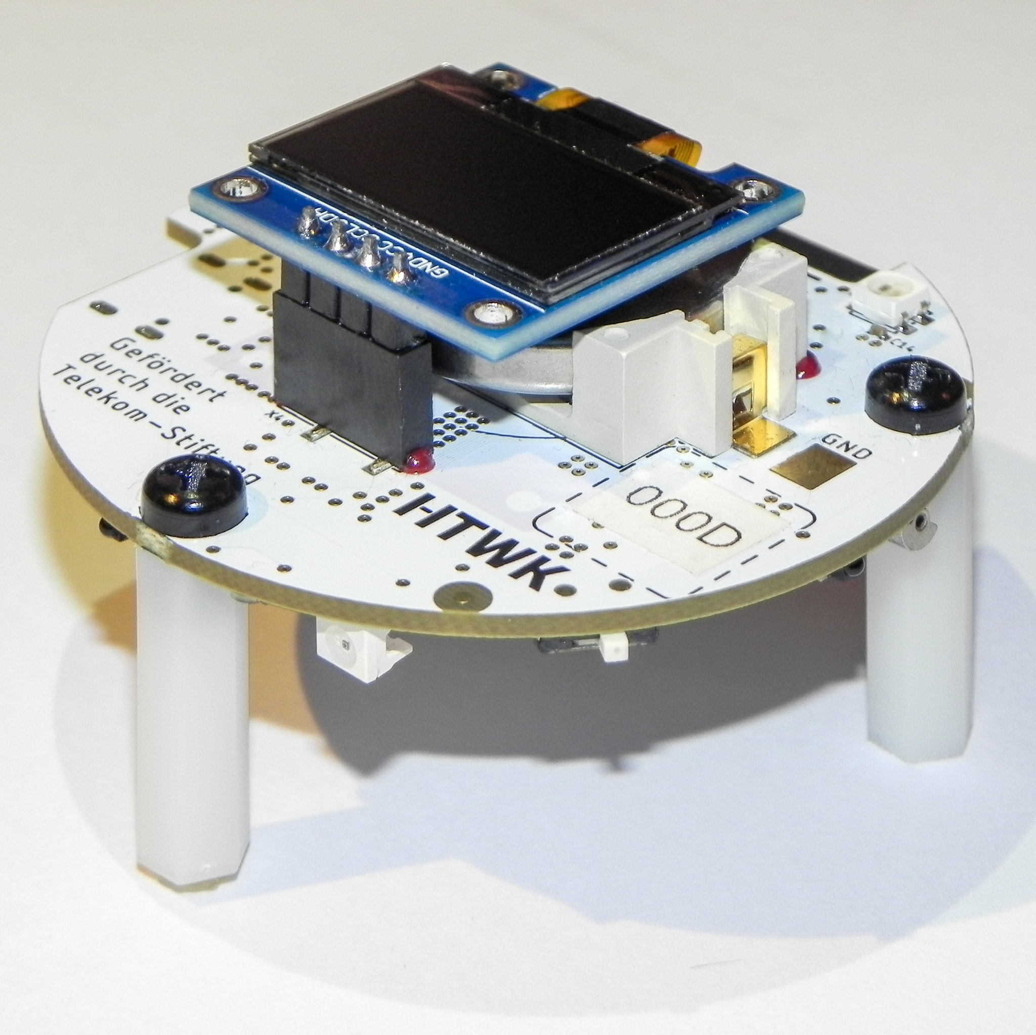
The Dezibot in its fourth iteration
This solution consists of three parts:
Power consumption analysis and modelling
To gain an overview over the initial situation, I created a measurement setup using a shunt resistor and an oscilloscope to measure the current consumption of the robot with high temporal resolution. This allowed me to identify load peaks and their causes, as well as to create a model of the current power consumption based on the robot’s activities, as managed by the software side.
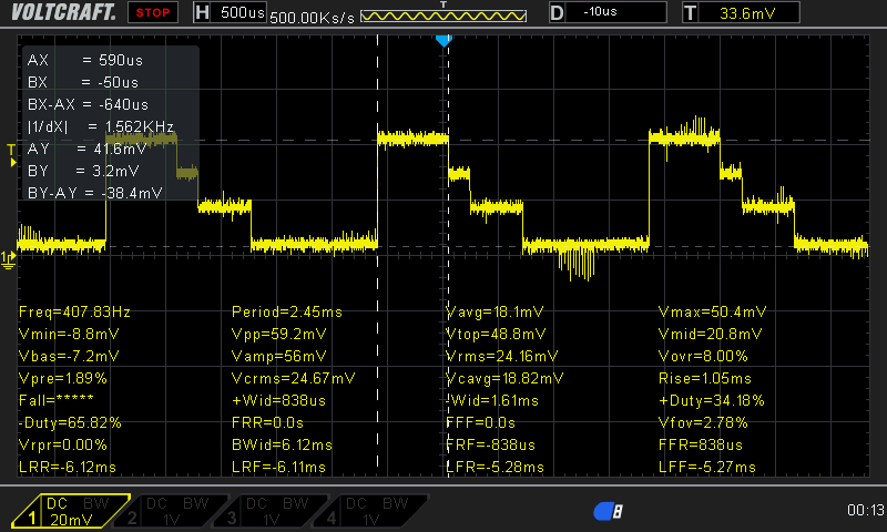
Example: Current flow through an WS2812B RGB LED set to a non-white color (1 mV = 1 mA)
Runtime modeling and accounting of power usage
To keep track of the current state of the robot during runtime, a class called
PowerManager, providing utilities for general modelling of the robots power state, such as battery charge and power supply state.In addition,
PowerManagerwraps a second class, thePowerScheduler, which uses the aforementioned measurements to keep track of all power-consuming components of the robot, such as motors, LEDs and sensors, as well as their current state. Based on this, it can estimate a current power consumption of the robot without actual facilities for measurement.
Example of current flow as modeled by the PowerScheduler
Runtime intervention and information in the user program
The overview gained in the first two steps is then used to modify runtime behaviour. A classical power management is not applicable in this context, as the actual program running on the robot is written by the user via the Arduino IDE.
To get around this the depot library, the intended abstraction layer for users of this robot, has been modified to cooperatively coordinate power usage with the
PowerScheduler. In the case of there not being enough power budget left over to safely run the intended action, the user is informed through the (default UART) serial output of the ESP32, and the action not carried out. In typical usage, this means that informative messages appear in the serial monitor of the Arduino IDE instead of the robot displaying unexpected and difficult to understand behaviour (e.g. resets or crashes), which would be detrimental to the intended use case.Example of such output:
9:21:21.767 -> [ 15441][W][PowerScheduler.cpp:167] waitForCurrentAllowance():
[Power] Task 0x3fcec210 timed out waiting for 12.000000 mA of power;currently
allocated: 155.925003 mA;total available (norm/max): 120.000000/240.000000 mA

9:21:21.798 -> [ 15460][W][MultiColorLight.cpp:41] setLed(): [MultiColorLight]
Power to set LED RGB TOP RIGHT to color 0x0096002B not granted in time. Skipping.
DMX-Board (2024) Link to heading
As part of the study module “Microcontroller Applications”, I developed this board and the associated software in collaboration with my fellow student Tom Wahl. The technical basis is an ESP32 microcontroller from Espressif.
The original aim as part of the module was to enable simple recording and playback of light programmes, i.e. incoming data on the input including their timing.
After the module was completed, the hardware was then extended to include GPIO terminals at the request of the professor. The aim was to be able to use the circuit board as a demonstration and test object in lectures.
My focus in this project was on the software: The software submitted during the module was developed directly using the ESP-IDF, without the Arduino framework. The DMX bus and the interaction elements (OLED display, encoder) are controlled via separate FreeRTOS tasks. This ensures that the operation of the DMX bus is prioritised.
In addition, the DMX bus is controlled via the ESP32’s DMA controller. This makes sense as the DMX bus is usually controlled by a central node (whose role we assume here), the controller. A DMX transmission with data for all 512 channels of a DMX universe requires approx. 22 ms. If this is done at the usual frame rate of 40 FPS, you will notice that the DMX bus is almost continuously being sent on. However, as all the data is already known at the start of the transmission, it would be inefficient to carry this out using CPU time.
Using DMA, the microcontroller can operate the DMX bus and all other peripherals available for operation without any problems, as can be seen in the Logic Analyser screenshot.
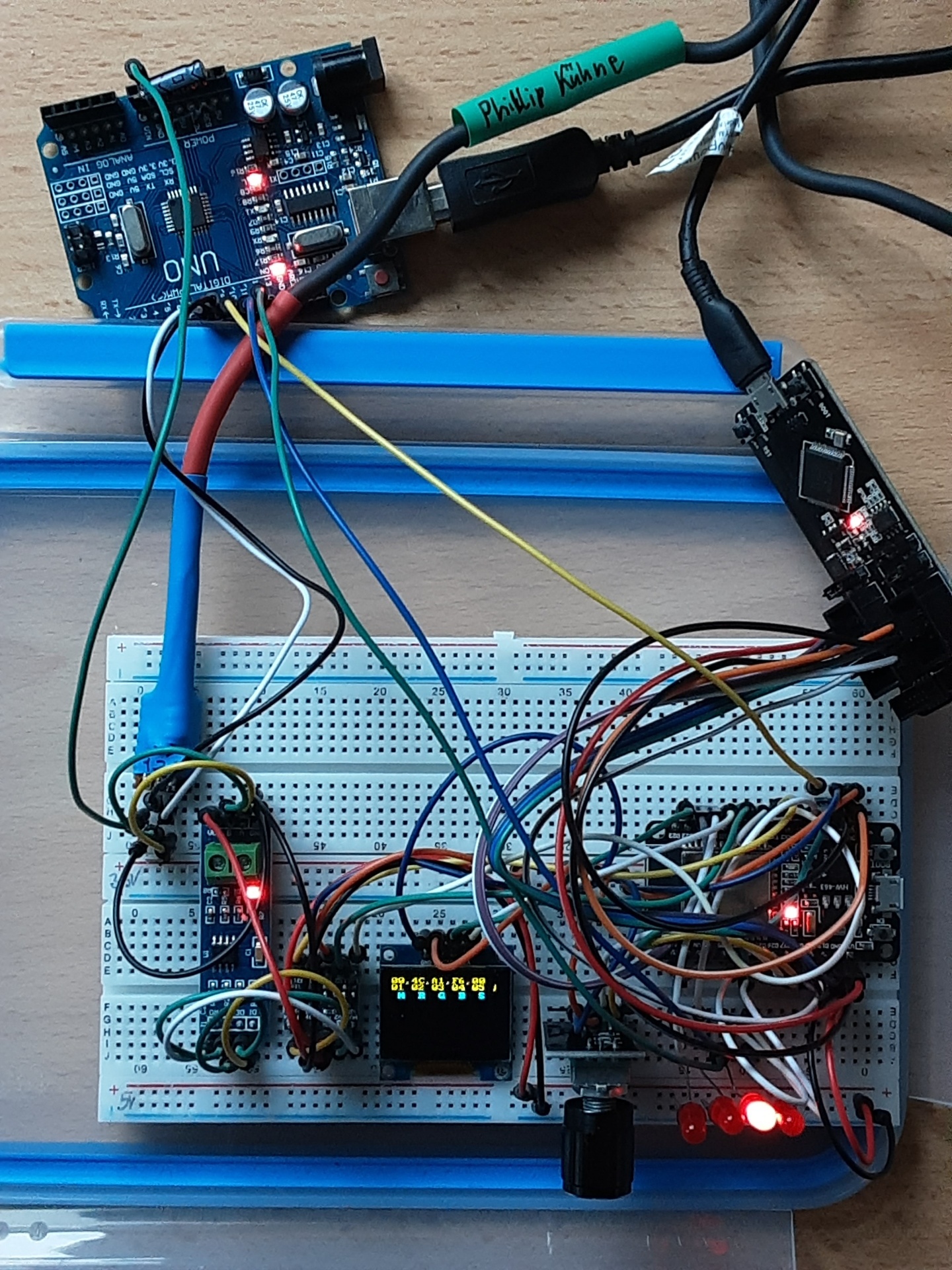
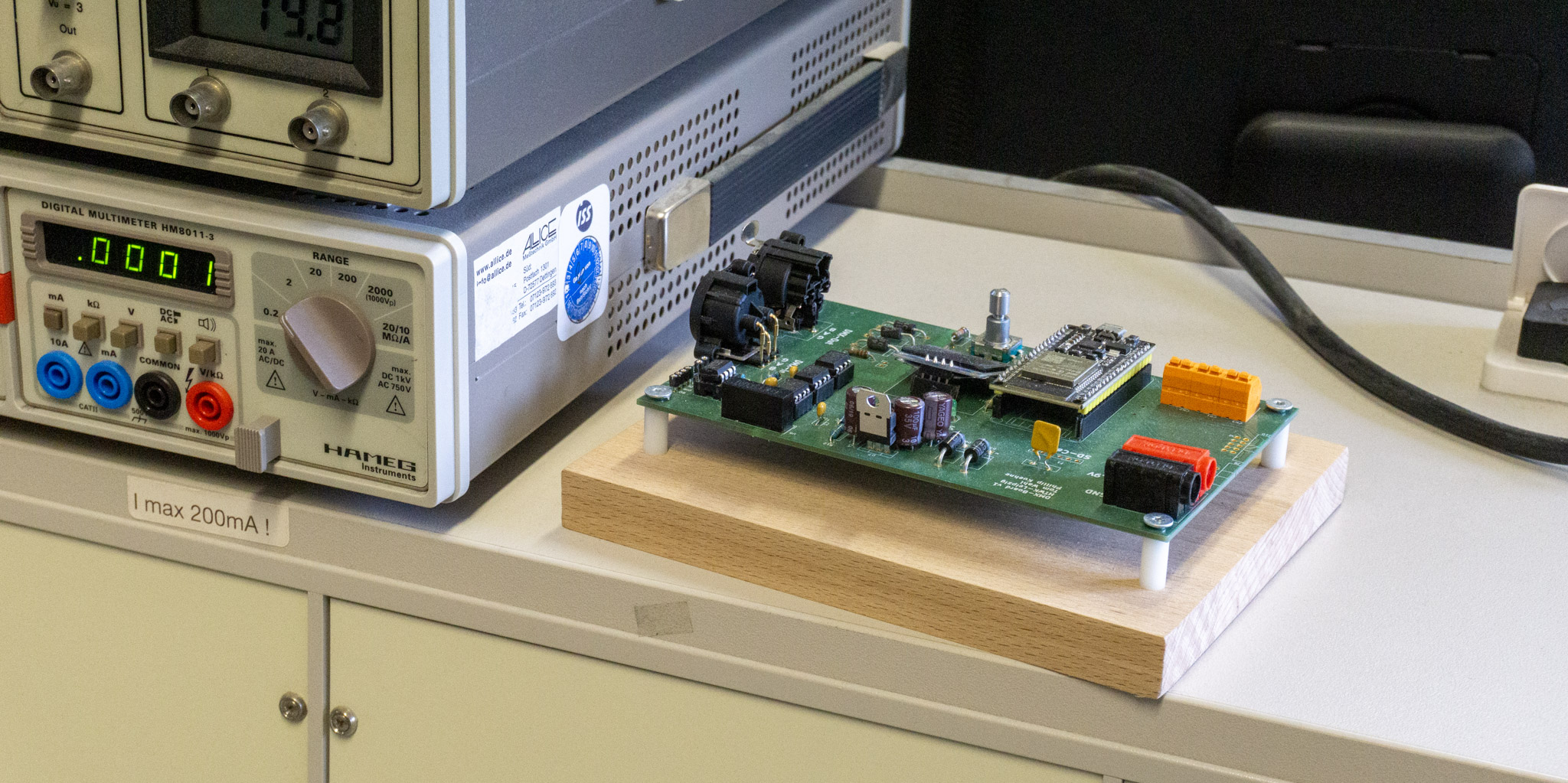
Experimental setup of the circuit on breadboard. The Arduino Uno in the upper part served temporarily as a logic analyser.
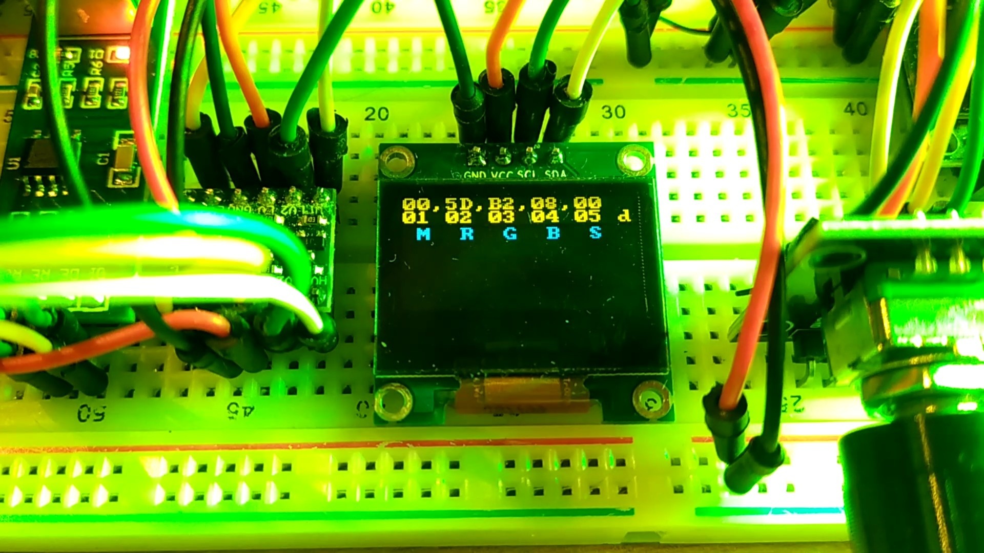
First software written for testing to control an RGB spotlight. M stands for Mode, S is an irrelevant additional parameter for RGB control (Mode 0).
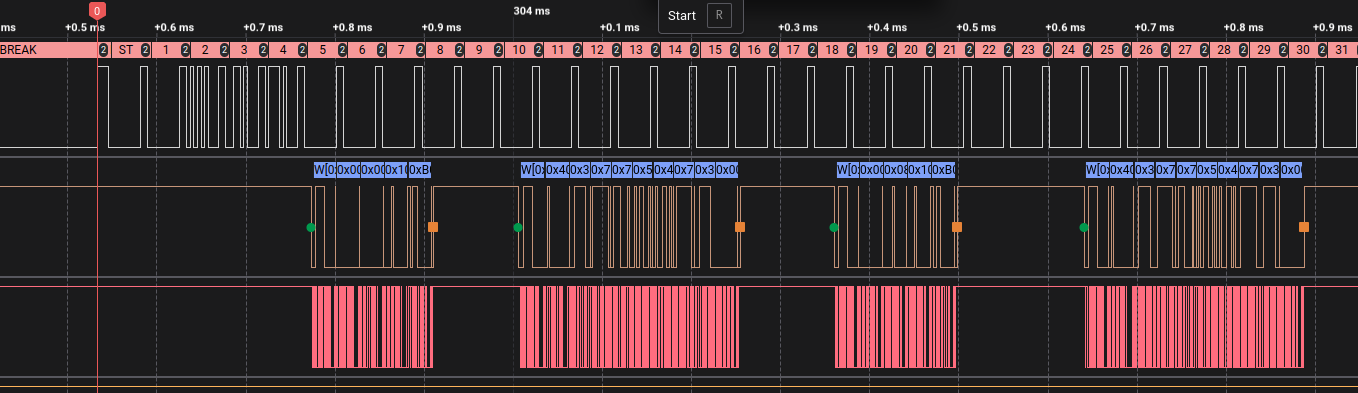
Concurrent activity on the various data buses. Top: DMX
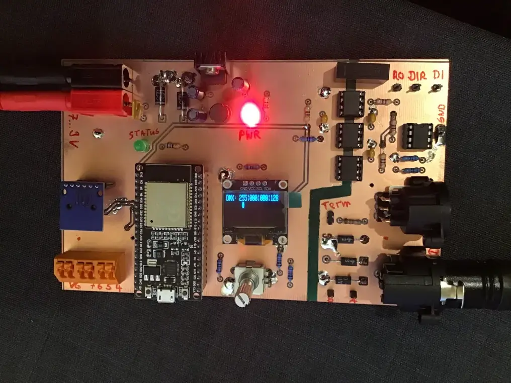
Circuit as a simple CNC-milled circuit board
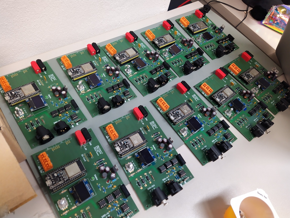
Manufactured Boards
Board after one year of use in teaching at HTWK Leipzig
KaraoQueue (2019) Link to heading
Guests can browse the song catalogue (with suggestions of the songs commonly sung during the previous events provided), view the metadata of the songs and queue in for their slot on the stage. The evening’s moderator can view the queue, and either accept or discard entries. If an entry is accepted, it is (anonymously) added to a playback list for the event, as well as to the statistics informing the suggestions.
It is written in Python, utilizing the Flask framework. Its architecture is very simplistic, for example, the frontend consists completely of handwritten Jinja templates, with everything (including handwritten JavaScript) contained inline. Bootstrap is used as the UI framework via static CSS/JS inclusion.
On the backend side, it utilizes a MariaDB for data storage, and can currently ingest Catalogue CSV files in the format provided by Recisio’s KaraFun. Playback statistics can be exported and imported, but will only work with the appropriate catalogue.
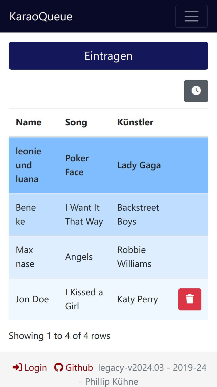
KaraoQueue main page screenshot
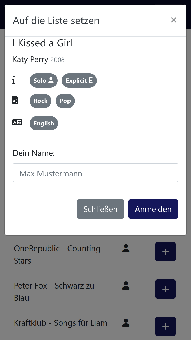
Metadata view for a song
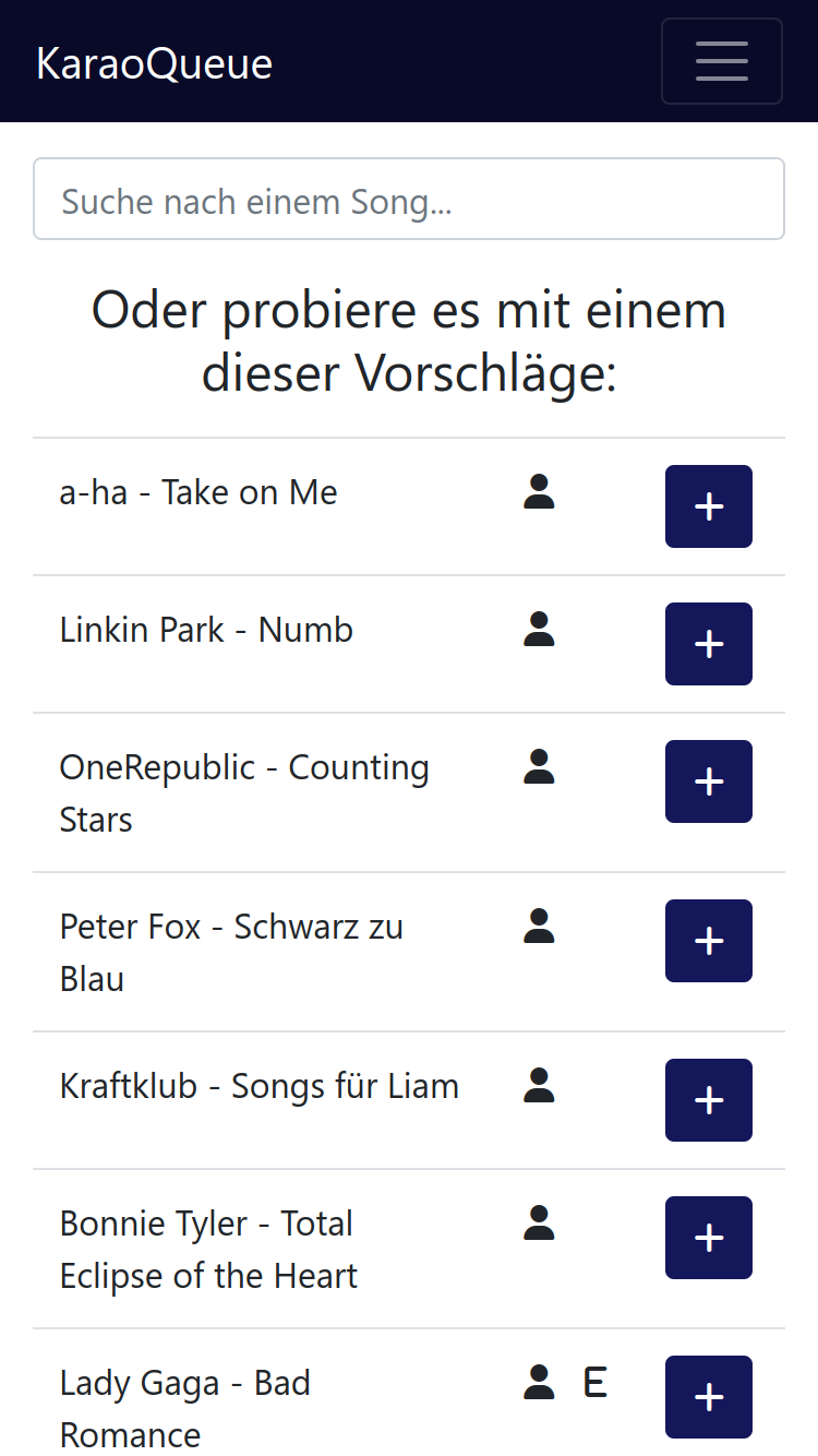
KaraoQueue song search with suggestions
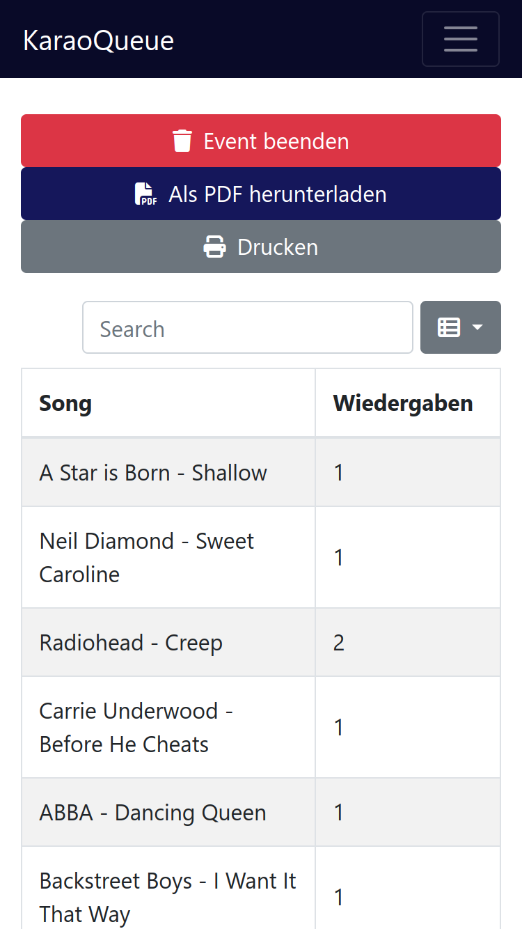
The list of played songs generated for an event